
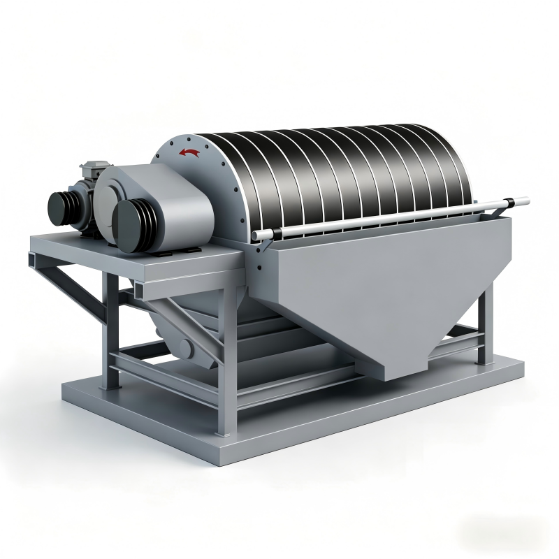
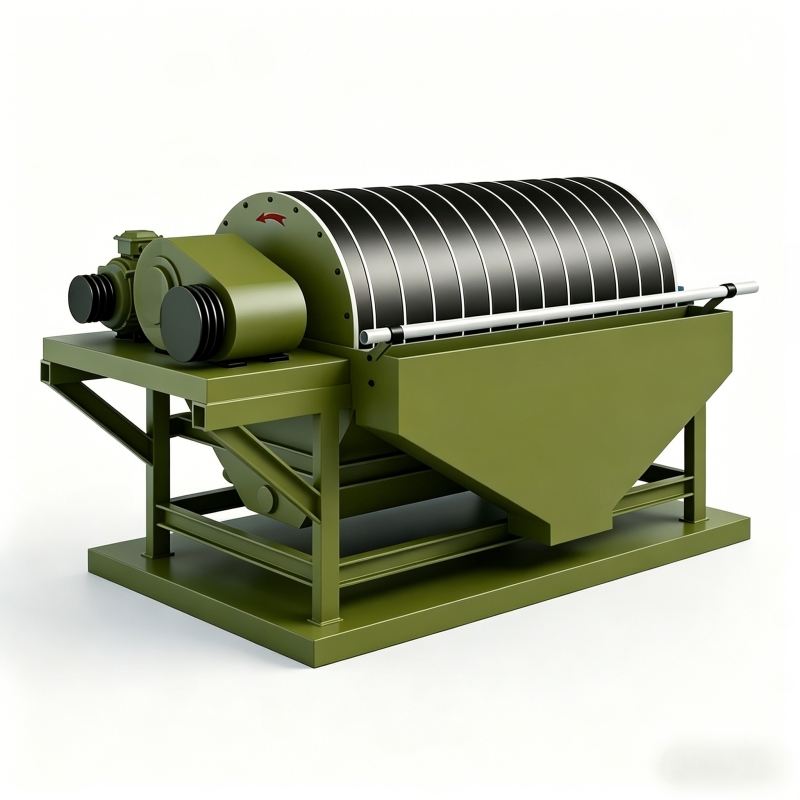
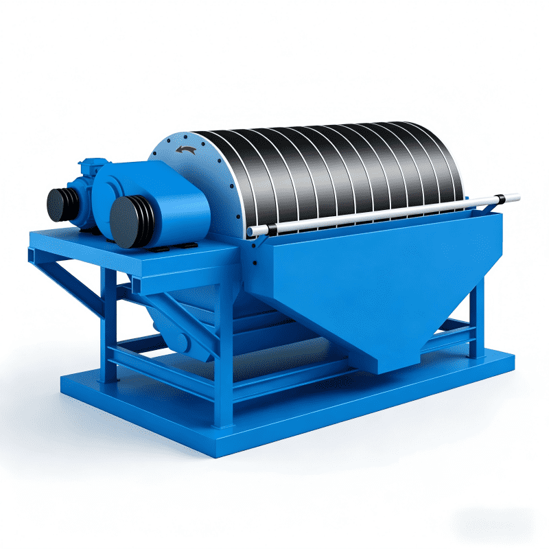
Magnetic Drum (Magnetic Pulley)
The structural principle of the magnetic drum (or magnetic pulley) is shown in Figure 7-10. The magnetic pulley is generally designed as a component of the head pulley of a belt conveyor. When magnetic material moves to the top of the magnetic pulley, it is attracted; when it rotates to the bottom, it is automatically discharged.
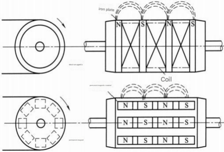
Figure 7-10 Schematic diagram of the magnetic pulley structure
Non-magnetic materials fall along a horizontal parabolic trajectory. This device can be used for removing tramp iron from material streams, as well as for the pre-concentration of lump iron ore.
Magnetic pulleys are used to remove tramp iron from materials conveyed by belt conveyors. Both electromagnetic and permanent magnetic pulleys can have diameters up to 1524 mm (60 inches) and widths up to 1524 mm. Electromagnetic pulleys can operate at belt speeds of up to 2.54 m/s (500 ft/min), while permanent magnetic pulleys can operate at belt speeds of up to 2.21 m/s (435 ft/min). Table 7-5 provides typical data for tramp iron removal magnetic pulleys. The data in the table are based on belt width. Look down the belt width column to find a value equal to or slightly greater than the required processing capacity, then move horizontally to the left side of the table to find the required magnetic pulley diameter. Then move horizontally to the right side of the table to find the recommended normal belt speed. If a higher belt speed is required, a larger diameter pulley must be selected. When selecting a magnetic pulley for an inclined belt conveyor, a correction factor must be applied to both the belt speed and the processing capacity, as listed in Table 7-6.
Table 7-5 Production capacity of magnetic pulleys for iron removal under normal conveyor operation ( m³/ h)
| pulley diameter
/mm |
Tape width/mm | Normal tape Velocity (m/s) | |||||||||||
| 305 | 356 | 406 | 457 | 508 | 610 | 762 | 914 | 1067 | 1219 | 1372 | 1524 | ||
| 305 | twenty two | 31 | 41 | 53 | 66 | 99 | 0.89 | ||||||
| 381 | 25 | 35 | 47 | 61 | 75 | 113 | 178 | 1.02 | |||||
| 457 | 29 | 39 | 53 | 69 | 85 | 127 | 201 | 297 | 1.14 | ||||
| 508 | 44 | 59 | 76 | 94 | 142 | 224 | 331 | 470 | 1.27 | ||||
| 610 | 67 | 87 | 108 | 161 | 255 | 377 | 538 | 742 | 1.45 | ||||
| 762 | 100 | 125 | 187 | 294 | 436 | 623 | 861 | 1.68 | |||||
| 914 | 138 | 207 | 326 | 481 | 688 | 951 | 1226 | 1.85 | |||||
| 1067 | 227 | 357 | 530 | 756 | 1042 | 1345 | 1671 | 2.03 | |||||
| 1219 | 246 | 385 | 575 | 821 | 1133 | 1461 | 1818 | 2.21 | |||||
| 1372 | 629 | 898 | 1237 | 1597 | 1985 | 2.41 | |||||||
| 1524 | 943 | 1303 | 1679 | 2090 | 2.54 | ||||||||
Table 7-6 Correction Factors for Inclined Conveyors
| Tilt angle / (°) | 5 | 6 | 7 | 8 | 9 | 10 | 11 | 12 |
| Correction coefficient | 0.955 | 0.946 | 0.937 | 0.928 | 0.919 | 0.910 | 0.901 | 0.892 |
| Tilt angle / (°) | 13 | 14 | 15 | 16 | 17 | 18 | 19 | 20 |
| Correction coefficient | 0.883 | 0.874 | 0.865 | 0.856 | 0.847 | 0.839 | 0.829 | 0.820 |
Magnetic drums (pulleys) are available in permanent magnet and electromagnetic types. They are used in ferrous metal mines to discard large waste rocks (350–10 mm) before ore beneficiation, thereby increasing the raw ore grade, improving processing capacity, and saving energy. Permanent magnet drums are widely used due to their simple structure, reliable operation, and energy efficiency. They have been standardized as ministry-level standards, with models ranging from CT-66 to CT-816, where the drum dimensions are D × L = 630 mm × 600 mm to 800 mm × 1600 mm. The technical characteristics of the domestically produced CT series permanent magnetic pulleys are shown in Table 7-7 [22].
Table 7-7 Technical specifications of CT series permanent magnetic pulleys
| Model | Drum size (mm) | Corresponding belt width (mm) | Magnetic field intensity on drum surface (kA/m) | Feed size (mm) | Processing capacity (t/h) | Mass (kg) |
| CT-66 | 630×600 | 500 | 120 | 10–75 | 110 | 724 |
| CT-67 | 630×750 | 650 | 120 | 10–75 | 140 | 851 |
| CT-89 | 800×950 | 800 | 124 | 10–100 | 220 | 1600 |
| CT-811 | 800×1150 | 1000 | 124 | 10–100 | 280 | 1850 |
| CT-814 | 800×1400 | 1200 | 124 | 10–100 | 340 | 2150 |
| CT-816 | 800×1600 | 1400 | 124 | 10–100 | 400 | 2500 |
To address the increasingly serious problem of ore dilution in current ferrous metal mines and to more effectively separate iron ores with relatively strong magnetic properties, magnetic pulleys are trending toward larger sizes and higher magnetic field intensities. The Eriez Company in the United States has developed an SR-E type magnetic pulley with an electromagnetic-permanent magnet composite magnetic system, which has been commercialized as a series product with eight specifications. The largest specification is: drum diameter × drum length = 2433 mm × 2438 mm.
To increase the magnetic field intensity of permanent magnetic pulleys, the magnetic pole material has been changed from strontium ferrite to cerium-cobalt-copper permanent magnet alloy, and the previously unfilled gaps between magnetic poles are now filled with cerium-cobalt-copper alloy.
Currently, in domestic magnetic pulleys, magnetic ores are separated by the attraction method. When the feed layer is thick, the magnetic ores on the upper layer, being subjected to weaker magnetic forces, are more likely to enter the tailings, increasing the tailings grade. A magnetic pulley with an electromagnetic-permanent magnet composite magnetic system developed in the United States uses the expulsion method to separate magnetic ores. The electromagnetic system is located above the separation point and is mainly used to expel magnetic materials. The permanent magnet system is arranged side by side with the electromagnetic system and is primarily used to hold the magnetic materials onto the drum surface, allowing them to be transported to the low-intensity magnetic field zone as the drum rotates.