
Types and Working Principle of Gyratory Crushers
A gyratory crusher is a type of cone crusher. Some refer to the gyratory crusher as a coarse crushing cone crusher. It is widely used for coarse crushing of various hard materials. When the feed size or equipment specification is the same, the production capacity of a gyratory crusher is more than twice that of a jaw crusher. Therefore, it is used as a primary crusher in large metal mines.
Depending on the drive and safety device, gyratory crushers are divided into hydraulic type and ordinary type [see Figures 1-15(a) and (b)]. Depending on the discharge method, they are divided into side-discharge type and center-discharge type [see Figures 1-15(b) and (c)]. Among these three types, the suspended-shaft center-discharge gyratory crusher is the most widely used.
The general structure of a gyratory crusher is shown in Figure 1-15(c). The body of the gyratory crusher is mainly composed of the crushing chamber, adjusting device, suspension device, and frame. The crushing chamber is an annular space formed by the moving cone (crushing cone) and the fixed cone. The moving cone is fixed on the main shaft. The upper end of the main shaft is supported by the crossbeam through the suspension device, and the lower end is inserted into the eccentric bushing.
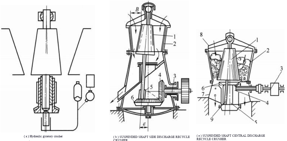
Figure 1-15 Schematic diagram of the gyratory crusher structure
1—Moving cone (crushing cone);2—Fixed cone;3—Drive shaft;4—Small bevel gear;5—Eccentric bushing;6—Large bevel gear;7—Frame;8—Crossbeam for suspending the main shaft; 9—Main shaft
When the eccentric bushing drives the main shaft to rotate via the large and small bevel gears, the moving cone performs a gyratory motion centered at the suspension point. During this motion, the moving cone alternately approaches and recedes from the fixed cone. When the moving cone approaches, the fed material is crushed between the moving cone and the fixed cone by compression and bending; when the moving cone recedes, the material in that section is discharged downward. After being repeatedly crushed in this manner, the material is discharged from the bottom of the crushing chamber.
The surfaces of both the moving cone and the fixed cone are lined with manganese steel liners or toothed plates. As the lower part of the moving cone liner wears continuously, the discharge opening width and the product particle size gradually increase. Therefore, adjustment is required using the adjusting device at the upper end of the main shaft. To adjust the discharge opening width, first remove the shaft cap, use a crane to slightly lift the main shaft upward, take out the wedge key, and then turn the conical nut clockwise or counterclockwise to raise or lower the main shaft and the moving cone, thereby decreasing or increasing the discharge opening width. When the required discharge opening width is achieved, insert the wedge key and refit the shaft cap.
The overload protection device of an ordinary gyratory crusher typically uses a safety pin installed on the drive pulley. Once an uncrushable object enters the crushing chamber and causes an overload, the pin is sheared off, and the machine stops running.
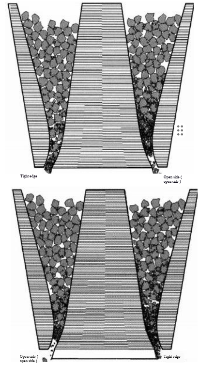
Figure 1-16 High-Fidelity Simulation (HFS) of the crushing mechanism of a gyratory crusher
The inner and outer surfaces of the eccentric bushing are lined (or welded) with Babbitt metal, but the outer surface is only lined with Babbitt metal on 3/4 of its area. To prevent dust from entering moving parts such as the eccentric bushing, an oil baffle ring and a sealing sleeve ring are installed at the lower part of the moving cone.
Viewed from above the gyratory crusher, the crushing chamber is annular. Therefore, the material inside the crushing chamber is also subjected to bending action. Moreover, at any given moment, part of the material is being compressed by the moving cone, while the material on the opposite side is being discharged downward. As a result, the machine operates continuously. Figure 1-16 shows a high-fidelity simulation (HFS) of the crushing mechanism of a gyratory crusher.
Construction of the Gyratory Crusher
The structural diagram of the hydraulic gyratory crusher is shown in Figure 1-17. The hydraulic cylinder is installed at the lower part of the crusher main shaft and is used to support the weight of the moving cone and the main shaft. It consists of a cylinder body, a piston, friction disks, etc. At the upper part of the hydraulic cylinder, there are three friction disks: the upper friction disk and the lower friction disk are respectively fixed on the main shaft and the piston, while the middle friction disk has a spherical upper surface and a flat lower surface. During crusher operation, both the spherical upper surface and the flat lower surface of the middle friction disk slide relative to the upper and lower friction disks. The discharge opening size can be adjusted by changing the oil volume inside the hydraulic cylinder.
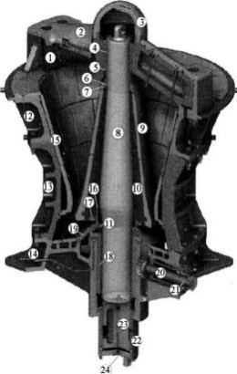
Figure 1‑17 Structure of a hydraulic gyratory crusher (image courtesy of FLSmidth)
1—Spider;2—Spider liner;3—Spider cap;4—Spider bushing;5—Spider oil seal;6—Threaded main shaft bearing;7—Head nut;8—Main shaft;9—Moving cone (mantle);10—Mantle centre body;11—Segmented contact oil seal;12—Upper frame;13—Middle frame;14—Lower frame;
15—Fixed cone (concave);16—Dust seal cap;17—Dust seal ring;18—Eccentric sleeve;19—Gearbox guard;20—Horizontal shaft;21—Horizontal shaft seal;22—Hydraulic cylinder;23—Piston;24—Moving cone position sensor
Hydraulic system of the gyratory crusher (Figure 1‑18)
The hydraulic system of the gyratory crusher is shown in Figure 1‑18. The pre‑charge pressure in the accumulator is 1100 kPa. Before starting the crusher, the hydraulic cylinder is filled with oil. To fill the cylinder, close shut‑off valve 4b, open shut‑off valve 4a, and start the single‑stage vane pump. When the oil pressure reaches 8–1100 kPa, the moving cone begins to rise. After it reaches the working position, close shut‑off valve 4a and stop the vane pump. At this point, the cylinder pressure of the hydraulic system balances the crushing force generated during operation.
This hydraulic system serves both as the discharge opening adjustment device and as the overload protection device for the gyratory crusher.
To increase the discharge opening width, open shut‑off valves 4a and 4b; oil in the cylinder flows back to the vane pump under the weight of the moving cone. When the moving cone has descended to the desired position, immediately close the valves.
To decrease the discharge opening size, open shut‑off valve 4a, start the oil pump to fill the cylinder with oil; the moving cone begins to rise. When the required discharge opening size is reached, close shut‑off valve 4a and stop the oil pump.
When an uncrushable object enters the crushing chamber, the force on the moving cone increases sharply, and the cone forcibly presses the piston downward. This causes the oil pressure in the cylinder to exceed the gas pressure in the accumulator. Oil is then forced from the cylinder into the accumulator, the moving cone descends, the discharge opening enlarges, and the uncrushable object is discharged. After the object is expelled, oil flows slowly from the accumulator back to the cylinder through the one‑way throttle valve, allowing the moving cone to return slowly to its original position.
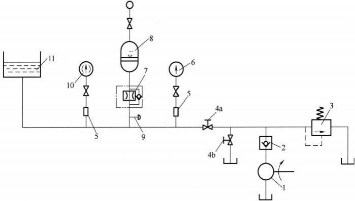
Figure 1-18 Schematic diagram of the hydraulic system of a gyratory crusher
1—Single‑stage vane pump;2—Check valve;3—Relief valve;4a, 4b—Shut‑off valves;5—Shock absorber; 6—Pressure gauge; 7—One‑way throttle valve; 8—Accumulator;9—Bleed valve; 10—Electrical contact pressure gauge; 11—Cylinder
Currently, gyratory crushers produced by various countries are all developing toward larger scales. The main parameters of large‑scale gyratory crushers are shown in Table 1-8.
Table 1-8 Main parameters of large gyratory crushers
| Crusher manufacturer | Specification / mm | Moving cone diameter / mm | Feed opening size / mm | Motor power / kW | Equipment mass / t | Capacity / (t/h) |
|---|---|---|---|---|---|---|
| Metso Outotec | 1524×2794 | 2794 | 1524 | 1200 | 390 | 10000 |
| Sandvik | 1650×3022 | 3022 | 1650 | 1100 | 824.5 | 6160~10940 |
| FLSmidth | 1600×3000 | 3000 | 1600 | 1200 | 525 | 6208~9490 |
| ThyssenKrupp | 1600×3300 | 3300 | 1600 | 1500 | 495 | 6200~14400 |
At present, the largest gyratory crusher in the world is the 1600 mm × 2896 mm gyratory crusher manufactured by ThyssenKrupp (Germany), used at the Grasberg copper‑gold mine in Irian Jaya, with a capacity exceeding 1000t/h