Screen-Side Air Chamber Jig
The screen-side air chamber jig is named for its use of an air-driven water pulsator instead of a piston to drive water movement. This machine is widely used in coal preparation, and in some foreign mines, it is also used for separating iron ore and manganese ore.
In the screen-side air chamber jig, the air chamber is located on one side of the machine body. This type of jig is also known as the Baum jig. For domestically produced equipment, the screen area ranges from 8 m² for smaller units to 16 m² for larger ones. According to application, it is classified into lump coal (13–125 mm) jigs, fine coal (0.5–13 mm or 0–13 mm) jigs, and raw coal (0–50 mm) jigs.
The basic structure of the screen-side air chamber jig is shown in Figure 6-4. It consists of components such as the machine body, air valve, screen plate, and discharge device. Compressed air is periodically admitted into or exhausted from the air chamber by the air valve, causing the water surface in the air chamber to form a pulsating flow. Top water enters through a supplementary water pipe located at the lower part of the air chamber to adjust the jigging cycle characteristic curve. Another portion of water, called flush water, is added together with the feed material from the feed end to wet the material. Together, the top water and flush water form a horizontal flow in the jigging chamber to transport the material. After stratification, the refuse and middlings are discharged through the discharge mechanisms of the refuse section and the middlings section, respectively, to the lower part of the machine body. There, they combine with the fine material that has passed through the screen plate and are discharged together by a bucket elevator. The clean coal is discharged from the overflow port to the outside of the machine.

Figure 6-4 Schematic diagram of the screen-side air chamber jig
1—Machine body; 2—Air valve; 3—Screen plate; 4—Discharge device; 5—Supplementary water pipe
Under-Air-Chamber Jig (Batac Jig)
In many applications, the Baum jig still exhibits good operating performance and can handle large quantities of raw coal with a wide size range (throughput up to 1000 t/h). However, because the stratification force in the Baum jig is distributed on one side of the jig, it causes uneven force distribution across the width of the jig screen plate, leading to uneven stratification. This can reduce the separation efficiency between coal and heavy impurities. In relatively narrow jigs, this tendency is less significant, and in the United States, multilayer floating layers and gate mechanisms are used to mitigate this effect.
The Batac jig is also pneumatic (Figure 6-5), but unlike the Baum jig, it has no side air chamber [3]. Instead, several air chambers are arranged across the entire width of the jig, typically two per cell, thereby ensuring uniform air distribution. This type of jig uses electronically controlled air valves that can precisely cut off the air supply and exhaust. Both the intake and exhaust valves can be arbitrarily adjusted according to stroke and frequency, allowing the desired variations in pulsation and suction to produce suitable stratification for raw coals with different characteristics. Therefore, the Batac jig is very effective for washing both coarse coal and fine coal [4]. The jig can also be successfully applied in iron ore processing to separate high-grade lump ore and produce concentrates for sinter feed, where heavy medium technology cannot upgrade the iron ore [5,6]. Production data for the Batac jig used for hard coal separation are shown in Table 6-7 [7].
For the Batac jig, the pulsation frequency is 45–55 min⁻¹ when the feed particle size is 150–10 mm, and 50–60 min⁻¹ when the feed particle size is 50–8 mm.
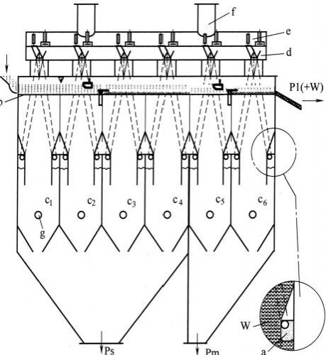
Figure 6-5 Batac jig
A—Feed; b—Jig screen plate; c₁~c₆—Air chambers; d—Air receiver (air chest); e—Air valve; f—Exhaust pipe with silencer; g—Bottom water pipe; P1—Clean coal; Ps—Reject (refuse/rock); Pm—Middlings; W—Water; a—Air chamber
By reducing the pulsation amplitude of the jig and increasing the pulsation frequency, as well as modifying the discharge port structure for heavy products, it is possible to beneficiate fine particles by jigging. The Batac jig can also process coal with a feed particle size of 3–0.1 mm. In this case, the pulsation amplitude is 20–5 mm, and the pulsation frequency is 70–100 min⁻¹. When processing a feed particle size of 150–10 mm, the pulsation amplitude is 200–100 mm, and the pulsation frequency is 45–55 min⁻¹. The optimal operating conditions should be adjusted according to the particle size variation of the material being separated.
The domestically developed LTX series under-air-chamber jig has a maximum screen area of 35 m² and can wash raw coal with a particle size range of 0–100 mm without prior classification. Its designed processing capacity is 350–490 t/h. It employs numerically controlled electromagnetic air valves and an electromagnetic调速 (speed control) system with a float for automatic discharge control. The operation is sensitive and reliable, making it suitable for large-scale coal preparation plants with an annual capacity of 3–4 million tons.
Table 6-7 Production data of Batac jig for hard coal separation
| Item | Example 1 | Example 2 |
| Feed particle size / mm | 150–10 | 10–0.5 |
| Capacity per unit jigging area (based on three-product separation) / [t/(m²·h)] | 18–20 | 12–14 |
| Capacity per unit screen width / [t/(m·h)] | 108–120 | 72–84 |
| Bottom water volume per unit bed area / [m³/(m²·min)] | 1.0–1.2 | 0.4–0.6 |
| Working air flow rate / [m³/(m²·min)] | 6.0 | 3.5 |
| Working air pressure of jig / bar① | 0.45 | 0.4 |
| Item | Example 1 | Example 2 |
| Working air pressure of blower / bar | 0.6 | 0.6 |
| Control air consumption per air chamber / (m³/min) | 2.0 | 2.0 |
| Control air pressure of jig / bar | 5.0 | 5.0 |
| Control air pressure of compressor / bar | 8.0 | 8.0 |
Power consumption of the jig (4 m × 6 m)
| Item | Example 1 | Example 2 |
| For working air / kW | 160 | 110 |
| For control air / kW | 75 | 75 |
| Hydraulic system / kW | 2×5.5 | 1.5 |
| Others / kW | 2 | 2 |
| Total / (kW·h/t) | 1.03 | 0.78 |
- 1 bar = 10⁵ Pa.
Hydraulic Drive Jig (ROMJIG)
The ROMJIG hydraulic drive jig is used as an example for illustration below.
In 1984, the German company KHD Humboldt Wedag developed the ROMJIG hydraulic drive jig, as shown in Figure 6-6 [8]. The ROMJIG mainly consists of a tank body, a double-lane elevator wheel, a jigging material rocker arm, a reject discharge wheel, a collecting hopper, a hydraulic system, and an electrical control system.
The reject discharge control of the ROMJIG operates as follows: a pressure sensor measures the load on the jigging mechanism (under stable bed thickness conditions, an increase in reject quantity increases the load). A regulator then controls the rotational speed of the hydraulic motor, achieving automatic control of the reject discharge rate. The material that passes through the screen plate of the ROMJIG is discharged through a closed hydraulic valve to a coal slurry screen for dewatering and recovery.
The ROMJIG is a single-end drive type. One end of the screen box is fixed with a pin shaft at its extended end, while the other end is driven by a hydraulic cylinder to move up and down. The ore moves along the slope of the screen surface. After stratification, the heavy product is discharged by the discharge wheel, while the light product overflows over the weir plate. The two products fall separately into the partitioned elevator wheel, which lifts them and then discharges them into launders for removal from the machine.
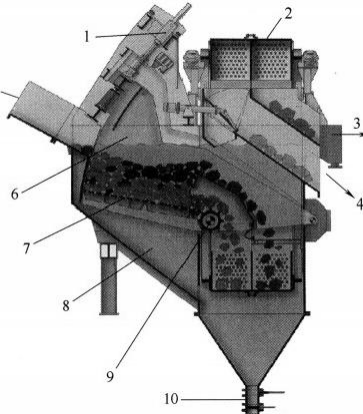
Figure 6-6 ROMJIG moving-screen jig
1—Hydraulic cylinder; 2—Bucket elevator wheel; 3—Clean coal; 4—Reject (rock); 5—Raw coal inlet; 6—Rocker arm; 7—Moving screen; 8—Under-screen chamber of the jig; 9—Reject discharge; 10—Fine coal discharge valve
This machine is used for the pre-concentration of coarse raw coal, with a feed particle size range of 300–25 mm. The screen plate area is 3.6 m², with a screen opening of 15 mm. The processing capacity reaches 300 t/h. The maximum stroke of the screen plate is 500 mm, and the stroke frequency is 25–40 times/min. The additional water consumption is only 10–15 m³/(unit·h). The hydraulic system pressure is 10.8–13.7 MPa, and the total power is 55 kW. This machine has been applied in coal mines in the Essen region of Germany.
The characteristic of this jig is that the screen plate is movable. The feed end of the screen plate is lifted hydraulically and descends by gravity. The pulsation frequency is 38–43 min⁻¹. The technical specifications of the ROMJIG moving-screen jig are shown in Table 6-8.
Table 6-8 Technical specifications of the ROMJIG moving-screen jig
| Item | ROMJIG 10.500.800 | ROMJIG 18.500.800 | ROMJIG 20.500.800 |
| Feed particle size / mm | 60–300 | 35–150 | 40–50 |
| Processing capacity / (t/h) | 150–170 | 300 | 350 |
| Effective screen plate area / m² | 2 | 3.2 | 3.6 |
| Rocker arm amplitude / mm | 300–500 (adjustable) | 300–500 (adjustable) | 300–500 (adjustable) |
| Rocker arm frequency / min⁻¹ | 30–50 (adjustable) | 30–50 (adjustable) | 30–50 (adjustable) |
| Elevator wheel speed / (r/min) | 0.7 | 1 | 1.2 |
| Elevator wheel power / kW | 11 | 15 | — |
| Total power of drive mechanism / kW | 86.88 | 95.5 | 110 |
| Coal preparation plants using this model in China | Laohutai | Xinji No. 2 Mine | Xinglongzhuang, etc. |
Other Types of Jigs
The Altair type centrifugal jig consists of a stationary cylinder equipped with launders for discharging light and heavy products, and a rotating bowl that spins inside the stationary cylinder (as shown in Figure 6-7). The rotating bowl contains a cylindrical screen, on which a bed of ragging material is placed, forming an artificial bed layer under the influence of a centrifugal force field. The feed slurry is introduced from the upper part into the center of the rotating bowl and is dispersed onto the surface of the artificial bed layer via a distribution plate. Pressure water is periodically injected into the back side of the artificial bed layer, causing the bed and the feed layer to alternately loosen and compact. High-density particles settle, pass through the artificial bed layer and the screen, and are recovered into the heavy product launder. Low-density particles that cannot pass through the artificial bed layer and the screen move to the lower end of the screen and are recovered into the light product launder. The centrifugal force during separation is 40–60 gf.
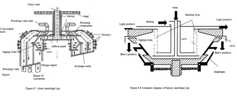
Kelsey Centrifugal Jig
A schematic diagram of the Kelsey type centrifugal jig is shown in Figure 6-8. On the circumference of the rotating rotor, there are many distribution plates (baffles), the upper parts of which are connected to the cylindrical screen inside the rotor. An artificial bed layer is formed on the screen plate under the influence of a centrifugal force field. The feed slurry is introduced through a feed pipe into the center and then into the artificial bed layer. Pressurized water periodically flows into each distribution plate, causing the particle layer on the screen plate to alternately loosen and compact. Low-density particles move on top of the artificial bed layer and are recovered from the upper part, while high-density particles pass through the artificial bed layer and the screen plate and are recovered as the heavy product. The centrifugal force during separation is 100 gf.
Filled Column Jig
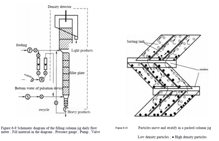
A schematic diagram of the filled column jig is shown in Figure 6-9. The filling column of this jig is equipped with serrated inclined screen plates or radial spiral screen plates (as shown in Figure 6-10). Particles enter the bottom of the filling column through the feed port. In the alternating upward and downward pulsating water flow, particles either rise or settle according to their density. As a result, low-density particles are discharged from the top of the filling column, while high-density particles are discharged from the bottom of the filling column. This jig features high separation accuracy.
In-Line Pressure Jig
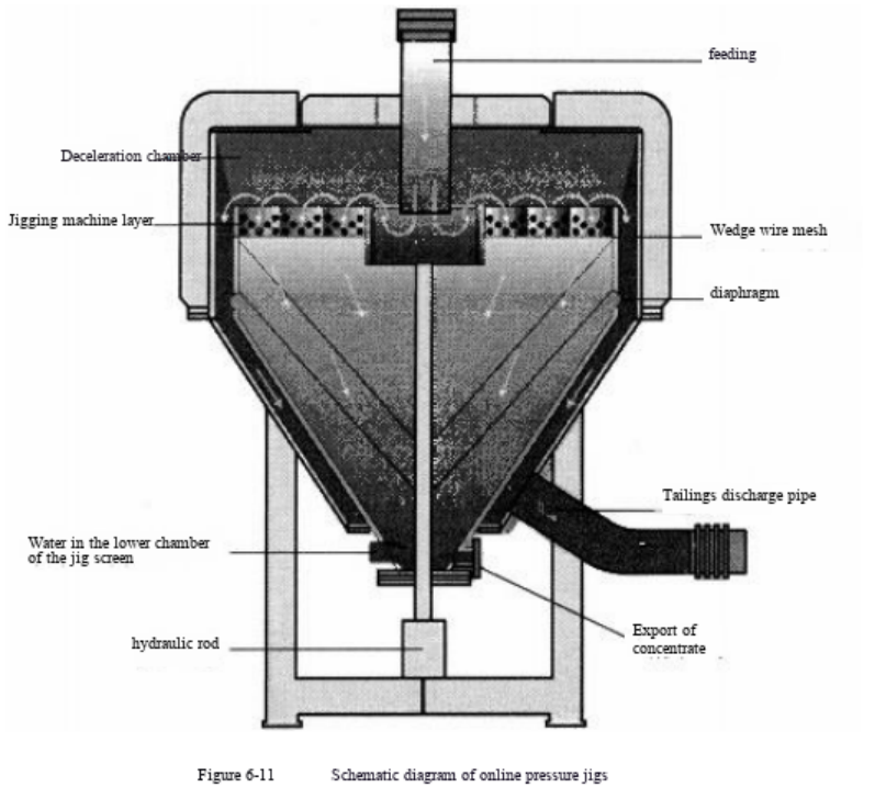
The in-line pressure jig is shown in Figure 6-11. This jig is a sealed device filled with water and slurry, always maintaining a maximum pressure of 0.2 MPa. The screen plate is circular, and a hydraulically driven shaft moves up and down. An artificial bed layer is placed on the screen plate. The feed is introduced from the central upper feed port onto the screen plate and moves up and down together with the artificial bed layer. High-density particles pass through the artificial bed layer and descend, while low-density particles move on top of the artificial bed layer and are discharged via the peripheral overflow weir. The advantage of the in-line pressure jig is that it can process particles with a feed size ranging from a few millimeters to 30 mm. Because it uses recirculated water, it reduces both water consumption and water treatment costs.