
Overflow Type Ball Mill
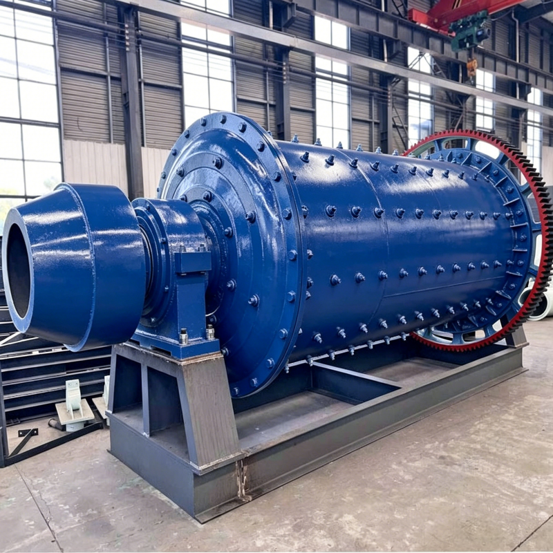
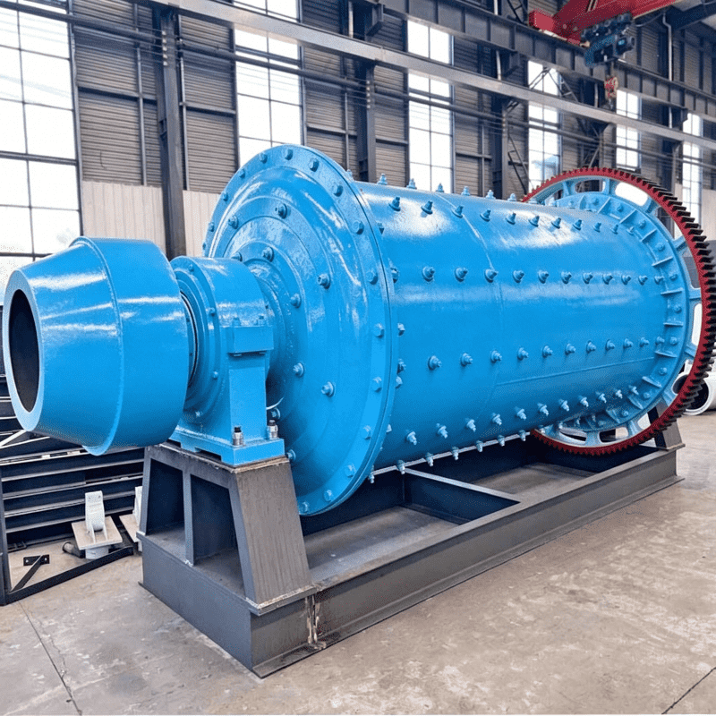
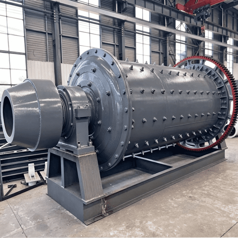
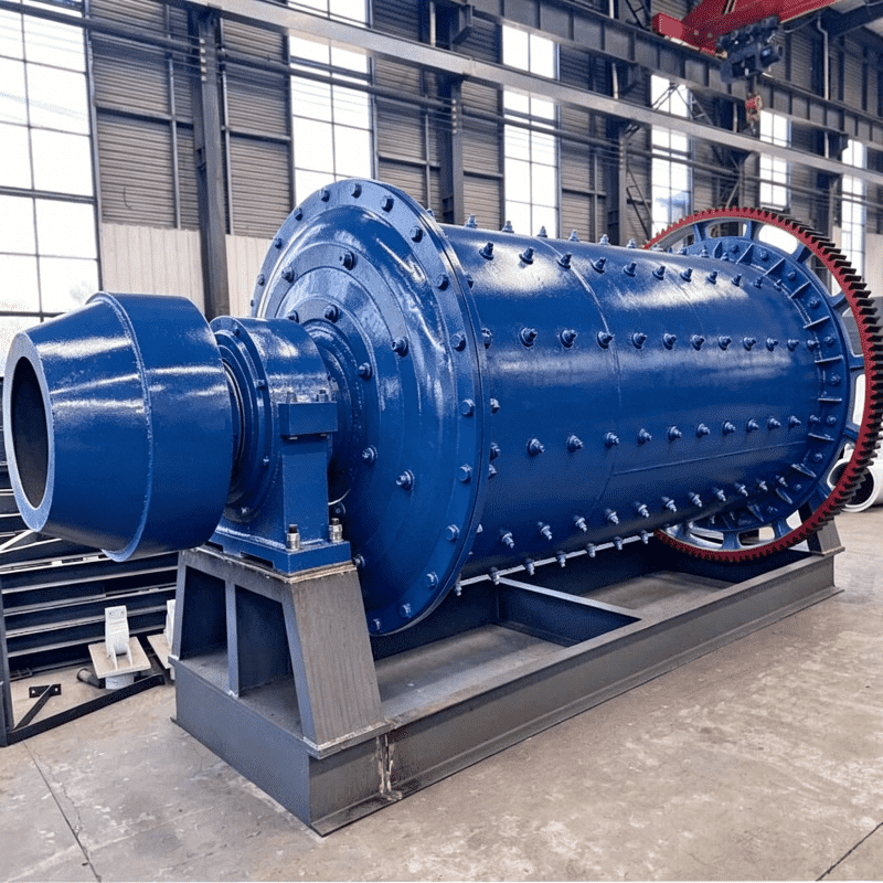
The shell of the ball mill (Figure 2-6) is welded from steel plates approximately 5∼36mm thick. Cast steel end covers are attached at both ends, connected to the shell via flanges. The hollow journals on the end covers are supported on main bearings. The inner walls of the shell and end covers are lined with liners. A large ring gear is fixed to the shell. A motor drives the pinion gear, which rotates the large ring gear and the shell. Material is fed through a feeder and the left hollow journal into the shell. The shell is filled with steel balls of specific diameter proportions as grinding media. The material is ground by the steel balls inside the shell and then overflows from the end cover and hollow journal out of the mill. The shell has 1∼2manholes for installing and replacing liners. The end cover and hollow journal are typically an integral cast steel part. The most common bearings used in ball mills are sliding bearings, which have a large diameter but short length. The bearing shells are lined with babbitt metal or made of machined bronze. The sliding bearings used in ball mills only have a semi-circular bearing shell at the bottom.
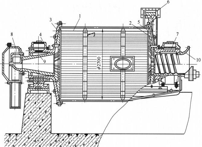
Figure 2-6 Overflow type ball mill
1—Shell; 2,3—End covers; 4,7—Main bearings; 5—Liner; 6—Large ring gear; 8—Feeder; 9,10—Hollow journals
The liners inside the shell not only protect the shell from wear but also their shape and size affect the motion pattern of the steel balls and grinding efficiency. Liner materials include high manganese steel, high chromium cast iron, hard nickel cast iron, medium manganese ductile iron, and rubber. Liner thickness is typically 50∼130mm. Materials like plywood, asbestos pad, rubber pad, etc., are placed between the liner and the shell to cushion the impact of steel balls and material on the shell. Liners are generally fixed to the shell with screws, with rubber and metal gaskets under the nuts for sealing.

Figure 2-7 Liner shapes
1—Single wave; 2—Double wave; 3—Step; 4—Wedge; 5—Lorrain bar and flat liner; 6—Flat-convex; 7—Rudder shape
Common liner shapes are shown in Figure 2-7. Smoother liners allow more relative sliding between steel balls and the liner, generating more grinding action, consuming less energy for lifting and throwing steel balls, and are suitable for fine grinding. Profiled liners provide strong lifting action for the steel balls, lifting them higher, resulting in strong cataracting action and strong agitation of the ball charge at the bottom. The shape, height, spacing, etc., of the liner profiles or lifters must be adapted to the material properties, steel ball size, and production requirements.
Rubber liners are wear-resistant, lightweight, easy to install/remove, produce less noise, can reduce processing cost per ton of ore, and are mainly used in secondary grinding and regrinding operations, offering better economic results than various steel liners. Common rubber liners include square, standard, and K-shaped types, as shown in Figure 2-8.
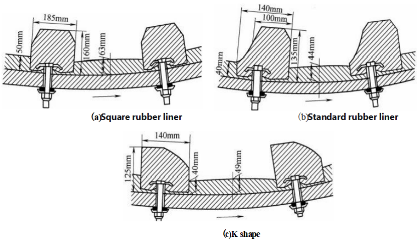
Figure 2-8 Rubber liners
Magnetic liners consist of ceramic permanent magnets embedded in rubber. The ceramic magnets firmly attach one side of the liner to the shell, while the other side attracts magnetic ore particles, forming a wear-resistant layer. After the wear layer is worn away, new magnetic particles are attracted, creating a cycle, hence also called “autogenous liners”, as shown in Figure 2-9. Using magnetic liners can reduce steel and energy consumption, showing good results in some industrial sectors.
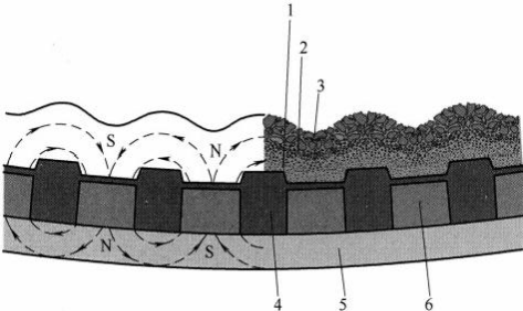
Figure 2-9 Magnetic liner
1—Homogeneous layer of fine magnetic material; 2—Layer of coarse magnetic material; 3—Fluidized layer of fine and coarse magnetic material; 4—Permanent magnet; 5—Mill shell; 6—Rubber
Large ball mills can use synchronous motors with pinion and large ring gear drives, or asynchronous motors with reducers, pinions, and large ring gears (Figure 2-10). The synchronous motor system has high transmission efficiency, small footprint, reliable operation, improves grid power factor, but is more expensive. The synchronous motor system requires an additional large reducer. Small ball mills may use synchronous motors with belt drives, pinions, and large ring gears, but transmission efficiency is low, footprint is large, and maintenance is complex. Ultra-large ball mills use ring motors (gear less drives).
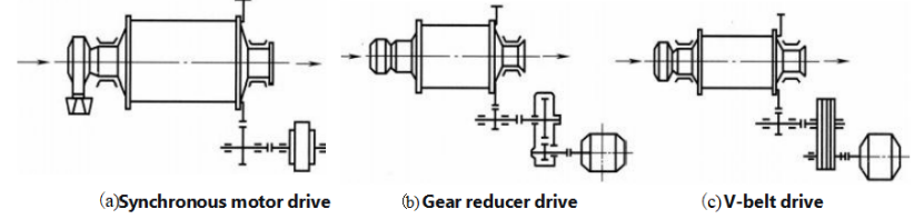
Figure 2-10 Drive systems for ball mills
The feed to the ball mill can be raw material, crushed product, or the coarse product (sands) from a classifier. Feeders introduce them into the mill for grinding. For dry grinding, simple chutes, screw feeders, disc feeders, etc., can be used. For wet grinding, drum-type, spiral-type, and combination feeders are commonly used.
The drum feeder [Figure 2-11 (a)] is mounted on the head of the ball mill’s hollow journal and rotates with it. It is used in open-circuit grinding systems for a maximum feed size of 70mm. The shell is welded from cast steel plate and has an internal spiral baffle. The cover is truncated conical with a feed opening on the left. Between the shell and the cover, a baffle has sector-shaped holes for material to enter the spiral section of the shell. Material enters the shell through the feed opening and sector holes and is lifted by the internal spiral lifter bars into the mill’s hollow journal. The spiral feeder has a spiral scoop [Figure 2-11 (b)] that, when rotating, scoops material from the trough below into the scoop. The material moves along the inner wall of the spiral scoop, is lifted, and fed into the hollow journal. The combination feeder (Figure 2-12) combines the functions of drum and spiral feeders. Raw material or crushed product enters through holes in the cover, is lifted by spiral lifter bars, and fed directly into the hollow journal. The circulating load (sands) is fed into the trough, scooped up by the scoop and scoop lip, and then fed into the hollow journal via the spiral lifter bars inside the shell. Feed cars are commonly used for feeding large ball mills.
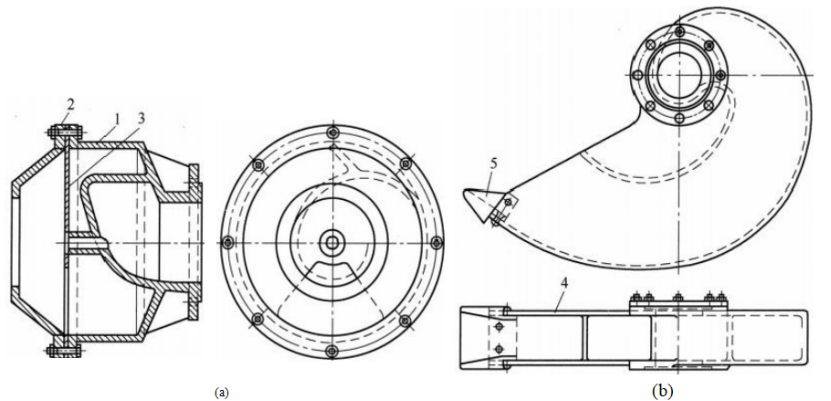
Figure 2-11 Drum and spiral feeders
1—Shell; 2—Cover; 3—Baffle; 4—Scoop; 5—Scoop lip