
Cone Crusher
Types and Construction of Cone Crushers
The so‑called cone crushers are generally used for medium and fine crushing of hard materials. The former is called the standard cone crusher, and the latter is called the short‑head cone crusher.
The basic construction of medium and fine cone crushers is essentially the same, and their working principle is similar to that of gyratory crushers. However, the main structural differences between a cone crusher and a gyratory crusher are as follows:
-
Support of the moving cone: In a cone crusher, the moving cone is not suspended from the crossbeam at the upper part of the machine by a main shaft. Instead, it is supported by a spherical bearing beneath the moving cone body.
-
Discharge opening adjustment: A gyratory crusher adjusts the discharge opening by raising or lowering the main shaft (and thus the moving cone). In contrast, a cone crusher adjusts the discharge opening by changing the vertical position of the fixed cone (adjustment ring).
-
Overload protection: A conventional gyratory crusher typically uses a hydraulic cylinder and accumulator as a protection device, whereas a spring cone crusher uses springs arranged around the machine frame as the protection device.
-
Crushing chamber shape: The cone crusher has larger cone angles for both the moving and fixed cones. When viewed from above, the diameter of the crushing chamber becomes larger as it approaches the discharge opening. In addition, there is a relatively long parallel zone near the discharge opening.
Spring Cone Crusher
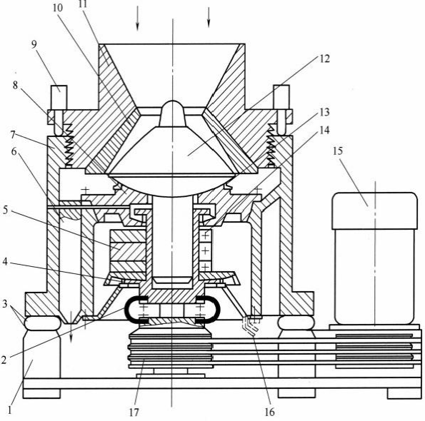
The main components of a spring cone crusher (Figure 1‑21) include the frame, moving cone, fixed cone, and springs. The crushing chamber is formed by the fixed cone and the moving cone. The surfaces of both cones are lined with wear‑resistant alloy steel liners. The fixed cone liner is attached to the adjustment ring. The outside of the adjustment ring is connected to the support ring by means of a zigzag (buttress) thread. The support ring cannot rotate. Turning the adjustment ring changes the vertical position of the fixed cone, thereby adjusting the discharge opening width.
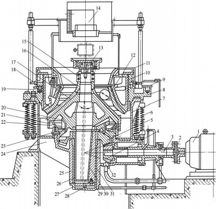
Figure 1‑21 Spring cone crusher
1—Electric motor;2—Coupling;3—Drive shaft;4—Small bevel gear;5—Large bevel gear;6—Safety spring;7—Frame;8—Support ring;9—Push cylinder;10—Adjustment ring;11—Dust cover;12—Fixed cone liner;13—Feed distributor;14—Feed hopper;15—Main shaft;16—Moving cone liner (mantle);17—Moving cone body;18—Lock nut;19—Piston;20—Spherical bearing bush (spherical socket);21—Spherical bearing housing;22—Spherical collar;23—Annular groove;24—Rib plate;25—Center sleeve;26—Bushing;27—Thrust disk;28—Lower frame cover;29—Oil inlet hole;30—Tapered bushing;31—Eccentric bearing;32—Oil outlet hole
The support ring is pressed against the periphery of the frame by a set of springs, and these springs serve as the crusher’s safety device. During normal operation, the springs generate sufficient pressure to balance the crushing force acting on the fixed cone. When an uncrushable object enters the crushing chamber, the force exerted by the moving cone on the fixed cone increases sharply, causing the springs to yield. This allows one side of the support ring and the adjustment ring to lift upward, increasing the discharge opening width so that the uncrushable object can be discharged. Afterwards, the spring pressure returns the support ring to its original position.
During operation of the cone crusher, to prevent dust from entering the spherical bearing and the drive components, a water‑seal dust protection device is installed on the spherical bearing.
The two cones (moving cone and fixed cone) of a cone crusher have a parallel zone near the discharge opening. To ensure that the crushed product achieves a certain fineness and uniformity, the parallel zone must have a sufficient length so that the material is subjected to at least one compression or crushing action in the parallel zone before being discharged. The length of the parallel zone depends on the required product particle size, the crusher size, and the type of crusher. According to the length of the parallel zone, cone crusher crushing chambers are classified as Standard, Intermediate, and Short‑head types, as shown in Figure 1‑22.
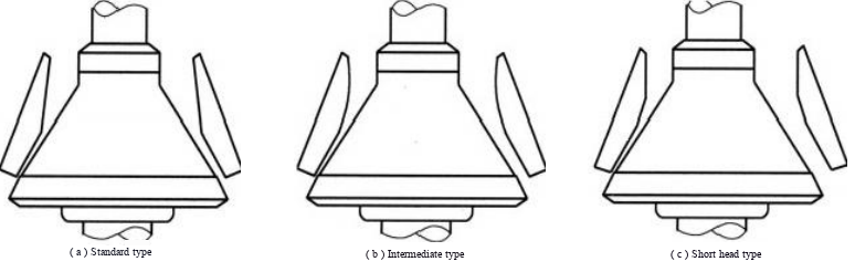
Figure 1-22 Shapes of standard, intermediate, and short‑head crushing chambers
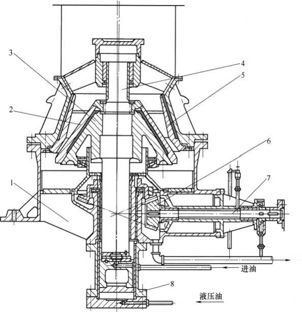
Figure 1‑23 Structure of a single‑cylinder hydraulic cone crusher
1—Rib plate;2,5—Liners;3—Moving cone;4—Main shaft;6—Small bevel gear;7—Drive shaft;
8—Hydraulic cylinder
1.4.1.2 Hydraulic Cone Crusher
All the types of cone crushers described above use springs as the safety device of the equipment. Practice has shown that this type of safety device has poor reliability and is prone to accidents such as shaft breakage. Moreover, adjusting the discharge opening on these crushers is very inconvenient. For this reason, hydraulic cone crushers have been vigorously developed and widely adopted both domestically and internationally.
Hydraulic cone crushers can be divided into single‑cylinder and multi‑cylinder types. In a multi‑cylinder hydraulic cone crusher, typically 12 to 24 hydraulic cylinders are used in place of the safety springs of the spring cone crusher, with the hydraulic cylinders serving as the protection device. The discharge opening adjustment of the multi‑cylinder type is still the same as that of the spring cone crusher. In a single‑cylinder hydraulic cone crusher, however, both the overload protection function and the discharge opening adjustment are accomplished by a single cylinder located at the lower part of the main shaft. Although the number and arrangement of cylinders differ, their working principles, basic structures, and hydraulic systems are similar.
As far as the crushing action and crushing process are concerned, the single‑cylinder hydraulic cone crusher is essentially the same as the spring cone crusher.
Figure 1‑23 shows the structure of a single‑cylinder hydraulic cone crusher. Compared with the spring cone crusher, the main features of this type of single‑cylinder hydraulic cone crusher are the use of hydraulic adjustment, hydraulic protection, and hydraulic unloading (for removing clogged material). The operating principle of the hydraulic adjustment and protection of the bottom‑type single‑cylinder hydraulic cone crusher is shown in Figure 1‑24.

Figure 1‑24 Operating principle of hydraulic adjustment and overload protection
Hydraulic oil is pumped under the piston of the hydraulic cylinder, causing the crushing cone to rise and the discharge opening to decrease, as shown in Figure 1‑24(a).
Oil under the hydraulic cylinder piston is returned to the tank, causing the crushing cone to lower and the discharge opening to increase, as shown in Figure 1‑24(b).
The high‑pressure oil under the hydraulic cylinder piston is connected to an accumulator. The accumulator is pre‑charged with nitrogen at a pressure of 502 kgf/cm² (1 kgf/cm² = 0.1 MPa, the same below). When an uncrushable object such as a piece of iron enters the crushing chamber, the vertical force pushing down on the crushing cone increases sharply, causing the oil pressure in the high‑pressure circuit to exceed the nitrogen pressure in the accumulator. The nitrogen is compressed, hydraulic oil enters the accumulator, and the piston together with the crushing cone descends. The discharge opening enlarges, the uncrushable object is discharged, and overload protection is achieved, as shown in Figure 1‑24(c).
After the uncrushable object is discharged, the nitrogen pressure is higher than the oil pressure during normal crushing. The oil that had entered the accumulator is forced back into the hydraulic cylinder, causing the piston to rise and the crushing cone to return to its normal working position.
A schematic diagram of the hydraulic system is shown in Figure 1‑25. The horizontal cross‑sectional area of the hydraulic oil tank is equal to that of the hydraulic cylinder. Therefore, the change in oil level indicated by the oil level indicator on the hydraulic tank corresponds exactly to the vertical displacement of the piston inside the hydraulic cylinder (and thus of the crushing cone). Using the proportional relationship between the vertical displacement of the crushing cone and the change in discharge opening, a discharge opening scale is provided on the oil level indicator. When adjusting the discharge opening, the operator can determine the change in discharge opening by reading the difference on the scale corresponding to the hydraulic oil level.
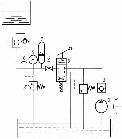
Figure 1‑25 Schematic diagram of the hydraulic system of a bottom‑type single‑cylinder hydraulic cone crusher
1—Oil tank;2—Oil pump;3—Check valve;4—High‑pressure relief valve;5—Manual directional valve;6—Shut‑off valve;7—Accumulator;8—Pressure gauge;9—Safety valve;10—Bleed valve;
11—One‑way throttle valve;12—Main hydraulic cylinder
In this type of crusher, the weight of the main shaft and the moving cone is fully supported by the oil pressure of the hydraulic cylinder. The hydraulic system consists of the hydraulic cylinder and piston, accumulator, oil tank, etc. When the discharge opening needs to be reduced, hydraulic oil is forced from the oil tank into the space below the piston of the cylinder; the moving cone then rises, and the discharge opening decreases. Conversely, when the discharge opening is to be increased, oil is allowed to return, and the moving cone lowers. The size of the discharge opening can be read directly from an oil level indicator. When an uncrushable object enters the crushing chamber, the oil pressure in the hydraulic circuit exceeds the nitrogen pressure in the accumulator (normally set at 5000 kPa). Hydraulic oil then flows into the accumulator; at the same time, the piston inside the cylinder and the moving cone descend together, enlarging the discharge opening and allowing the uncrushable object to be discharged, thus providing overload protection for the machine.
The single‑cylinder hydraulic cone crusher can easily be automated during the crushing process, and its weight is relatively low. This type of crusher has been widely used in China. The size of a cone crusher is indicated by the diameter D (mm) of the bottom of the moving cone. The largest cone crusher in the world today is the Metso MP2500 cone crusher, with an installed power of 2000 kW.
CALIBRATOR Cone Crusher
In the CALIBRATOR cone crusher (Figure 1‑26), the fixed cone liner is mounted on the upper frame, and the moving cone is supported on a spherical bearing. The spherical bearing is supported either by a hydraulic cylinder or by a set of annular springs, which are installed inside the main shaft. This crusher has some innovative structural features: the overload protection device and the discharge opening adjustment device are both located at the spherical bearing. One of the characteristics of the CALIBRATOR cone crusher using annular springs is its high damping capacity. When an uncrushable object enters the crushing chamber, the annular springs are compressed and deformed, causing the moving cone and the spherical bearing to yield downward. After the uncrushable object is discharged, the moving cone and the spherical bearing slowly return to their original positions, thereby reducing impact and minimizing liner wear. The width of the discharge opening is adjusted by turning a handwheel, which drives a bevel gear to raise or lower the spherical bearing. The vertical position of the moving cone is read from a pointer and a scale, allowing the discharge opening to be set to the required width.
This type of cone crusher is also available in a hydraulic version (Hydraulic CALIBRATOR), in which hydraulic cylinders replace the annular springs. It is equipped with four types of liners: standard, medium, fine, and extra‑fine.
Gyradisc Cone Crusher
The Gyradisc cone crusher manufactured by Metso Outotec (Figure 1‑27) is a fine crushing crusher. Its overload protection device, discharge opening adjustment device, spherical bearing, and other structural features are similar to those of a conventional short‑head cone crusher. However, the liners and the crushing chamber shape are quite distinctive: the parallel zone of the crusher has extremely short liners and a very gentle slope. As a result, a very thick “dense bed” of material is formed inside the crushing chamber, and the particles are crushed mainly by interparticle compression and attrition under the action of the moving cone.
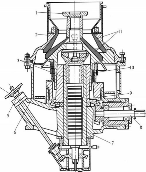
Figure 1‑26 CALIBRATOR cone crusher
1—Feed distributor (feed plate);2—Upper frame;3—Sliding bearing (sliding shoe);4—Handwheel;5—Scale (dial);6—Lower frame;7—Annular springs;8—Drive shaft;9—Main shaft;
10—Labyrinth seal;11—Liner
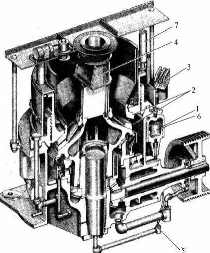
Figure 1‑27 Gyradisc cone crusher (image courtesy of Metso Outotec)
1, 6—Pneumatic overload protection device;2—Crushing plate (liner);3—Hydraulic adjustment device;4—Rotating feed distributor;5—Pressure oil lubrication system;7—Hydraulically controlled locking device
This effect is called interparticle crushing. Its advantages are, first, that a finer product size can be obtained at the same discharge opening width, and second, because the crushing action occurs mainly between particles, liner wear is reduced.
When using this type of crusher for secondary fine crushing of a certain material, the fine crushing product size can be reduced to 100% passing 7 mm (with a circulating load ≤50%) or 100% passing 3 mm (with a circulating load <150%), thereby increasing ball mill throughput and reducing energy consumption.
New Type Cone Crusher
(1) HKB Cone Crusher
A modern, new-type short-head cone crusher — the HKB cone crusher — is shown in Figure 1‑28. This cone crusher consists of a cylindrical lower frame, to which a vertical main shaft is fixed. The upper part of the main shaft is designed as a hollow shaft, which houses a vertically adjustable piston. The piston is equipped with a spherical bearing for axial guidance of the suspended moving cone. The radial support of the moving cone is provided by an eccentric bushing mounted between the moving cone and the main shaft. A bevel gear drives the eccentric bushing to rotate, causing the moving cone to perform a gyratory motion. The upper frame, which carries the fixed cone, is firmly bolted to the lower frame. The discharge opening width is adjusted by hydraulically raising or lowering the piston inside the main shaft.
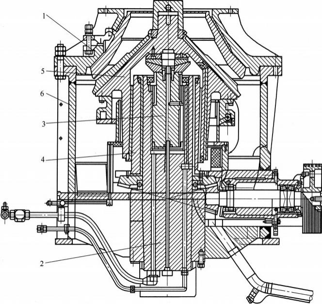
Figure 1‑28 HKB cone crusher (image courtesy of ThyssenKrupp)
1—Upper frame;2—Main shaft;3—Adjustable piston;4—Eccentric bushing;5—Moving cone;
6—Cylindrical lower frame
When a difficult‑to‑break foreign object passes through, once the preset hydraulic pressure is approached, the moving cone deflects downward, thereby protecting the equipment.
This cone crusher (model HKB1050) has been successfully used in slag and aggregate crushing. When crushing gravel, the capacity can reach 200 t/h with a feed size F₈₀ of 35 mm and a product size P₈₀ of 12 mm.
(2) Inertia Cone Crusher
The inertia cone crusher was successfully developed in the mid‑1980s by Mekhanobr Tekhnika Research and Design Institute (OAO Mekhanobr Tekhnika) in Russia. It can crush materials of any strength: from metal alloys to superhard ceramics, as well as from rocks to industrial waste, plant materials, and food. In the inertia cone crusher, an unbalanced vibrator is used as the drive for the crushing cone, replacing the traditional eccentric bushing that had been used in crushers for over 100 years. A schematic diagram of the inertia cone crusher is shown in Figure 1‑29, and its technical features are listed in Table 1‑15 [15,16].