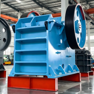

High‑Pressure Grinding Roller (HPGR)
The high‑pressure grinding roller, also known as a roller press, is a new type of crusher. Its external appearance is very similar to that of a conventional roll crusher, but its working principle, structure, and auxiliary equipment are quite different.
In the cement industry, HPGR is often combined with an air classifier (separator), sometimes also with a dispersing device, a ball mill, as well as other auxiliary equipment and control instruments, to form an HPGR grinding system. This system is a new comminution technology that began development in the 1970s and has gradually matured. The core equipment of this system is the high‑pressure grinding roller.
The advent of HPGR represents a breakthrough in comminution technology. In the building materials industry and other industrial sectors that require grinding systems, adopting or adding an HPGR generally brings significant economic benefits: it can greatly increase the system’s throughput while reducing the specific energy consumption (energy consumption per unit weight of material crushed).
1.8.1 Working principle
The two rolls of an HPGR apply a huge force (up to 20 MN) to the material, delivering the energy required for comminution directly to the material, which is crushed and compacted between the rolls into a so‑called “flake”. During this process, numerous cracks are generated inside the material particles, their structure is damaged, and the material becomes easier to crush (i.e., its grindability is improved).
Figure 1‑52 is a schematic diagram of the working principle of an HPGR. The two rolls are mounted on the frame. One roll is fixed (the stationary roll) and is rigidly attached to the frame; the other roll is movable and can slide along guides. The movable roll is pushed by a hydraulic system toward the material between the two rolls and toward the fixed roll. Material crushed to about 30 mm is fed through a chute into the wedge‑shaped space between the rolls, is gripped by the rotating rolls, and moves downward with them. During downward movement, the material is subjected to high pressure from the rolls, becoming compacted and crushed, and is finally discharged from the bottom. HPGR differs from conventional roll crushers: conventional roll crushers crush particles essentially individually, resulting in a coarse product. HPGR operates on the bed comminution principle, producing a large amount of fines, and the crushed product contains numerous cracks within individual particles, making subsequent liberation easier.
For an HPGR to work effectively, the following requirements must be met:
① To apply the required comminution energy and force to the material, a choke‑fed (material column) condition is used: the material is fed densely and uniformly into the wedge‑shaped zone between the two rolls. A buffer bin is usually placed above the rolls, slightly offset. This buffer bin is supported by load cells. Through the load cells, an electronic scale adjusts the feed rate to ensure that a material column of constant height is maintained in the chute from the buffer bin to the wedge zone. The pressure of this material column forces the material into the wedge zone, resulting in uniform feeding, smooth operation, and vibration‑free performance.
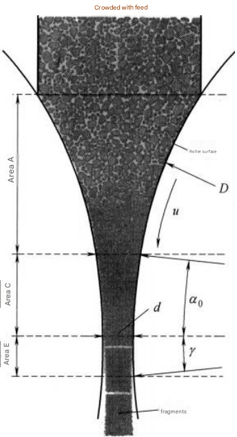
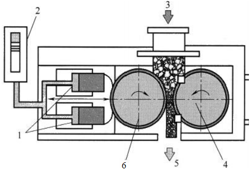
Figure 1‑52 Schematic diagram of the working principle of a high‑pressure grinding roller (HPGR)
1—Hydraulic cylinder;2—Nitrogen cylinder (accumulator);3—Feed;4—Fixed roll;5—Product;
6—Movable roll
① To apply the required comminution energy and force to the material, a choke‑fed (material column) condition is used: the material is fed densely and uniformly into the wedge‑shaped zone between the two rolls. A buffer bin is usually placed slightly above the midpoint between the two rolls. This buffer bin is supported by load cells. Through the load cells, an electronic scale adjusts the feed rate to ensure that a material column of constant height is maintained in the chute from the buffer bin to the wedge zone. The pressure of this material column forces the material into the wedge zone, resulting in uniform feeding, smooth operation, and vibration‑free performance.
② Due to the abrasion and wear caused by the high pressure between the roll surfaces and the material, the roll surface material must have good wear resistance, and the roll surfaces must be easy to repair and replace. In addition to crushing cement raw materials such as limestone and cement clinker, HPGR is also used for crushing highly abrasive materials such as metallic ores. For the latter, the wear resistance of the roll surface is especially important.
③ The machine structure and all components must be robust and reliable to withstand the enormous forces and transmit the crushing power. The four rolling bearings that support the rolls, in particular, require extremely high technical specifications.
④ A complete control and automation system must be provided.
Main structure of the high‑pressure grinding roller (HPGR)
The main structure of an HPGR includes the roll bearings, drive unit, main frame, hydraulic system, and feeding device, etc. The structure of an HPGR is shown in Figure 1‑53.
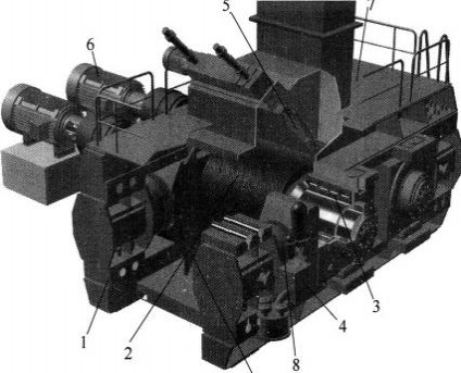
Figure 1‑53 High‑pressure grinding roller (HPGR)
1—Frame;2—Grinding roll;3—Bearing system;4—Hydraulic unit;5—Hydraulic cylinder;6—Inspection door;7—Drive;8—Feeding device;9—Operating platform
Roll Surface Structure
Currently, roll surface structures are divided into two major categories: smooth roll surface and grooved roll surface, of which the grooved roll surface is the most widely used. Grooved roll surfaces are further subdivided into weld‑deposited grooved roll surfaces, studded (column pin) roll surfaces, and machined groove/pocket roll surfaces. The service life of the roll surface and the ease of its maintenance are key to HPGR performance.
(1) Weld‑deposited roll surface
In terms of wear‑resistant roll surfaces, the earliest approach was to weld‑deposit wear‑resistant alloy onto a solid roll. The solid roll was made of high‑strength steel. Because it was difficult for the material of a solid roll to simultaneously meet the requirements of high strength and good weldability for the weld overlay, the design was changed to a roll composed of a tire (shell) and a shaft, each made of a suitable material, with the tire shrink‑fitted onto the shaft. Wear‑resistant alloy is weld‑deposited onto the tire. The weld overlay must be wear‑resistant but not too hard (approx. 60 HRC) to prevent spalling (cracking) under stress.
(2) Cemented carbide stud (column pin) roll surface
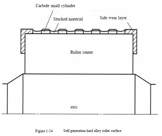
Self‑generating cemented carbide roll surface: Short cylindrical cemented carbide inserts are embedded into the roll surface in a matrix pattern (Figure 1‑54). When material is compressed, it becomes wedged between the short cylindrical studs, forming a self‑generating liner made of the material itself, which protects the roll surface. Even for highly abrasive materials, the service life of this roll surface exceeds 2000 hours. This design also withstands occasional pressure peaks caused by hard tramp material, grips the material well, and prevents slipping on the roll surface, thereby increasing throughput. This is particularly advantageous for moist and fine feeds [19].
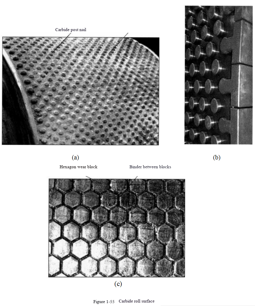
Due to its improved wear resistance, the studded roll surface [Figure 1‑55(a)] has become standard in new designs, especially in hard‑rock applications. Most roll surfaces use a self‑generating wear layer, i.e., crushed material is captured on the roll surface and retained in the gaps between the studs, forming a protective wear layer, with side protection of the studs as shown in Figure 1‑55(b).
The Hexadur® roll surface is commonly used in cement applications, as shown in Figure 1‑55(c). This roll surface uses a patented wear‑resistant material. The roll surface structure consists of many regular hexagonal wear blocks, with a softer binder material between each hexagonal block.
The regular hexagonal wear blocks are made of powder metallurgy cemented carbide. They have high strength, good wear resistance, ductility, and fracture toughness, but their service life is relatively short.
Main Bearings
Given that the enormous forces of the HPGR rolls are supported by the main bearings, the requirements for the bearings are very high. The bearing design and lubrication must be perfected, and the bearings must have a long service life. For models smaller than RP10, KHD Humboldt Wedag uses conventional self‑aligning roller bearings. For models larger than RP10, a new type of radial bearing with four rows of cylindrical rollers (Figure 1‑56) is used to withstand the huge radial forces, together with a small thrust bearing to absorb the axial forces. The four‑row cylindrical roller bearing uses a new circulating thin‑oil lubrication system instead of conventional grease lubrication (Figure 1‑57).
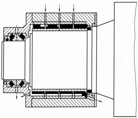
Figure 1‑56 Radial bearing with four rows of cylindrical rollers
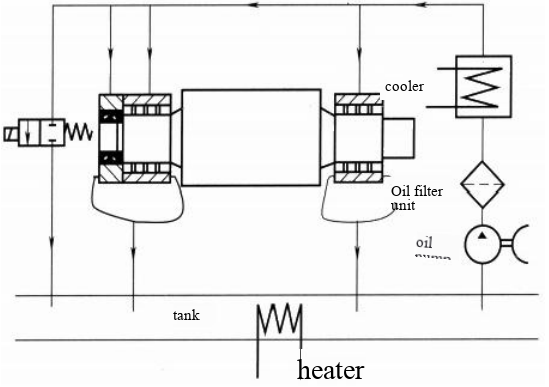
Figure 1‑57 Schematic diagram of the grease lubrication system
Drive System
To accommodate the horizontal movement of the movable roll while maintaining parallelism between the two rolls, the drive system of the roller press can be roughly divided into the following types. In one type, the roll shaft is directly connected to a planetary reducer via a coupling, and the electric motor is mounted on the reducer and drives through V‑belts; the entire drive mechanism moves together with the roll shaft. In another type, the electric motor is placed on the floor and connected to the roll shaft via a universal coupling and a reducer, with the universal coupling accommodating the oscillation between the two rolls. Both of the above are dual‑drive systems. However, single‑drive systems also exist, where one motor and one reducer are connected to both roll shafts through two couplings.
Main Frame
The main frame is of welded construction, consisting of an upper beam, a lower beam, and columns, which are bolted together. The forces between the rolls are transmitted by shear pins in the steel structure, so that the bolts are not subjected to shear forces. Rubber elements are provided between the bearing housing of the fixed roll and the end of the base frame for cushioning. The bottom of the movable roll bearing is lined with PTFE (polytetrafluoroethylene), and a smooth nickel plate is riveted at the bearing housing supporting the movable roll. The main frame may also be hinged.
Hydraulic System
The hydraulic system is provided to apply pressure to the rolls. It mainly consists of an oil pump, an accumulator, hydraulic cylinders, control valves, etc. The accumulator is pre‑pressurized to a value lower than the normal operating pressure. When the system pressure reaches a certain value, feeding begins; the roll retracts, and pressure continues to be supplied until the operating setpoint is reached, at which point the oil pump stops. Under normal operation, the oil pump does not run. If the pressure in the system becomes too high, hydraulic oil is discharged into the accumulator, lowering the pressure and protecting the equipment. If the pressure continues to exceed the upper limit, the system automatically releases pressure. During operation, if the system pressure falls below the lower limit, the pump automatically starts to increase pressure.
Feeding Device
The feeding device is an important component for achieving choke‑fed (full) operation of the roller press. It consists of elastically supported side plates and an adjustable feed gate. The feed rate is adjusted to match the thickness of the material cake.
Technical Characteristics and Product Size of HPGR
The characteristics of HPGR are mainly as follows: When operating in open circuit as a pre‑grinding stage at the same product size, HPGR can increase the capacity of an existing ball mill circuit by 30–55%. Operating HPGR with a ball mill in a partial closed circuit can double (100% increase) the capacity of the original grinding circuit. HPGR achieves substantial savings in specific power consumption. Regarding wear of grinding media and liners, HPGR reduces wear to less than 1% compared with the first compartment of a dry multi‑compartment ball mill (also used for pre‑grinding), and to less than 0.1% compared with a wet ball mill or semi‑autogenous mill used for coarse grinding. The use of HPGR eliminates the need for intermediate crushing in many ore processing flows, increasing capacity. Operating costs are reduced. For a given capacity, the size of an HPGR is much smaller than that of a corresponding ball mill or SAG mill; the reduction in equipment size reduces the required building dimensions by 25–30%, thus relatively lowering capital costs.
Table 1‑28 lists the equipment specifications and capacities of major manufacturers [21]. KHD Humboldt Wedag (Germany) has been a pioneer in HPGR technology. Table 1‑29 shows the 12 series classified by the force between the rolls from this company.
Table 1‑28 Equipment specifications and capacities of major manufacturers
| Parameter | KHD | FLSmidth | Köppern | Polysius | Metso | FCB |
|---|---|---|---|---|---|---|
| Roll diameter (m) | 1–2.6 | 0.58–2.7 | 0.8–2.8 | 0.95–2.6 | 0.8–3.0 | 1.6–4.6 |
| Roll width (m) | 0.5–2.3 | 0.26–1.85 | 0.2–1.6 | 0.65–1.75 | 0.5–2 | 0.54–1.67 |
| Power (kW) | 280–6000 | 100–5800 | 150–4000 | 440–6800 | 220–11500 | 200–3800 |
| Capacity (t/h) | 30–4200 | 100–3000 | 35–2000 | up to 3000 | 70–4800 | 70–1200 |
*Note: The original table for FLSmidth shows “1003000”, which is likely a typo; it is interpreted as 100–3000 t/h.*
Table 1‑29 KHD HPGR specifications
| Series | Roll diameter D (mm) | Roll width W (mm) | Throughput G (t/h) | Weight (t) |
|---|---|---|---|---|
| RPS 7-140/110 | 1400 | 1100 | 400–900 | 94 |
| RPS 7-170/110 | 1700 | 1100 | 600–1300 | 109 |
| RPS 10-170/110 | 1700 | 1100 | 600–1300 | 122 |
| RPS 10-170/140 | 1700 | 1400 | 800–1600 | 134 |
| RPS 13-170/140 | 1700 | 1400 | 800–1600 | 160 |
| RPS 13-170/180 | 1700 | 1800 | 1000–2100 | 171 |
| RPS 16-170/180 | 1700 | 1800 | 1000–2100 | 210 |
| RPS 18-200/180 | 2000 | 1800 | 1400–2900 | 238 |
| RPS 20-220/200 | 2200 | 2000 | 1900–3900 | 314 |
| RPS 20-260/200 | 2600 | 2000 | 2600–5400 | 321 |
| RPS 24-300/200 | 3000 | 2000 | 3500–7200 | 397 |
| RPS 27-300/220 | 3000 | 2200 | 3900–8000 | 424 |
The feed size of an HPGR is similar to that of a cone crusher, but due to different crushing mechanisms, their product size distribution curves are different: HPGR generates many more fine particles. Figure 1‑58 shows the product size curves of iron ore crushed by an HPGR and by a cone crusher, respectively. For the same P₈₀, the cumulative passing 800 μm is 20% for the cone crusher product, whereas it is 44% for the HPGR product — a difference of 24 percentage points [22].
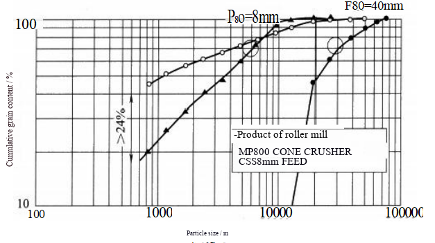
Figure 1‑58 Comparison of product size between HPGR and cone crusher (image courtesy: Weir Minerals)
Currently, the largest HPGR in production is the Polysius 24/16 model, with a roll diameter of 2.46 m and a roll width of 1.6 m. Each unit has a power of 2 × 2800 kW. Four such units are used at the Boddington gold mine in Australia.